It is obvious that the hardware requires power in order to function. But the power is not directly supplied to them. Most of the essential hardware components are embedded into the motherboard with printed circuits between them. The motherboard acts as the bridge to supply power to several internal hardware in a computer. Only the CD drive, HDD, and some other hardware receive power directly from the power supply unit. For others, you need to link the power connectors to the motherboard and attach the components to the respective port on the board. With this comprehensive guide, we are going to learn how to connect the power supply to the motherboard.
How to Connect Power Supply to motherboard?
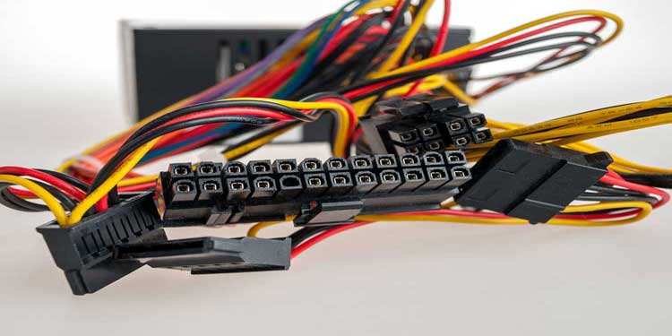
When you bring the power supply unit or PSU out of the box, you will see a number of wires with connectors at the end. Each of the connectors is meant to supply power for different hardware. It is quite confusing to find the right one for each of them. However, in the messy jungle of wires inside the casing, the hardware manufacturers have given us a slight advantage. The power supply connectors can be linked in only one way to the ports. That is, if you connect the wires in the wrong way, it won’t go in and you will know to flip it.So, let’s start to connect the power supply to the motherboard step-by-step by arranging a screwdriver set and the will to do the work.
Assemble the Power Supply Unit to the Casing
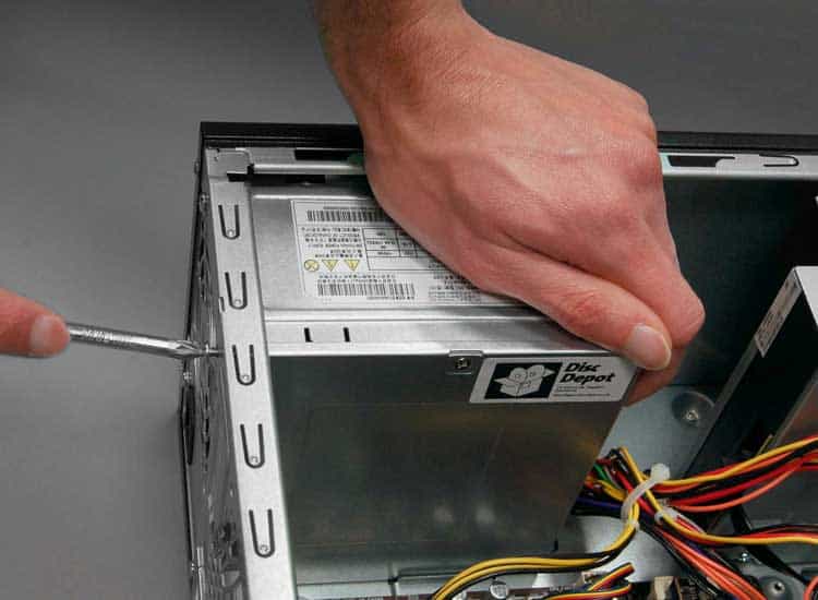
The first thing to do is to place the PSU in the CPU casing. Most of the casings have a box-shaped empty space at the top to keep the PSU. If you have modified your system and have bought a custom casing, then you will have to look at its manual to find the space.You can follow the instructions given below to assemble the PSU to the casing.Now that you have assembled the PSU successfully, let’s move on to connect the cables.
Connection of 20 (+4) pin motherboard Power Connector
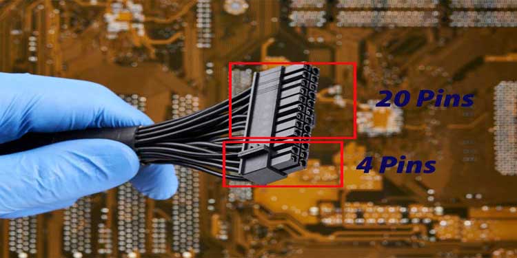
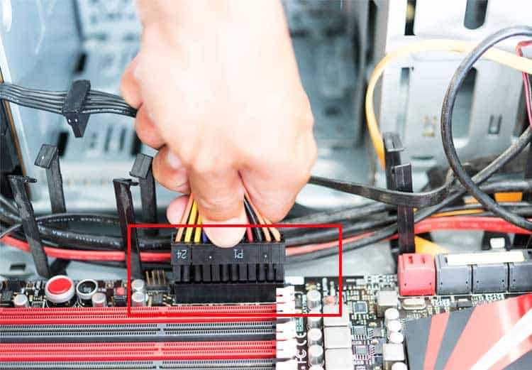
This cable is one of the biggest connectors and provides the juice to run your entire motherboard and its components.The reason we are writing the pin as 20 (+4) is that the connector has a bigger portion with 20 pins and a separate one with 4 pins. The reason behind this is to facilitate the older motherboards that had only 20 holes to insert the pins.Since it is the biggest port on the motherboard, except for the RAM and graphics card slot, you should not miss it.Let’s see how you can install the connector to your motherboard.Now, let’s look at the way to connect other power pins to the motherboard.
Connection of 4 (+4) Pin CPU Power Connector
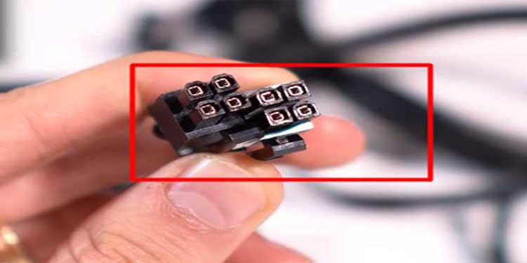
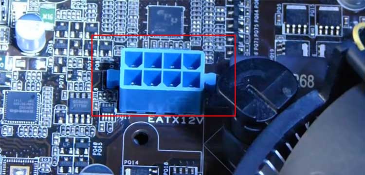
Another cable that your will find coming out of the power supply is a 4 (+4) pin CPU power connector. This cable supplies power to run your processor.This connector is also divided into two parts with 4 pins divided equally to each of them. You can use either only the single 4-pin part, or both parts depending on the motherboard’s requirement. Some motherboards with advanced features have more power requirements. The PSU designed for those boards even consists of two 8-pin connectors.But it does not matter how big the connector is. The process to connect it is the same. Here is how you do it.Your processor can work with just a 4-pin connector even if it has a port requiring 8-pins. However, it might malfunction due to insufficient power and I would not recommend doing that.But for the higher-end board with two 8 pins requirement, you can just insert one and it will do the job. You need to insert the remaining if you want to do extra pieces of stuff such as CPU overclocking.Now that you have powered your motherboard and CPU, let’s go to know about the other connectors.
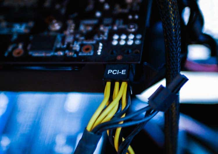
Connection of 6 (+2) Pin PCIe Connector
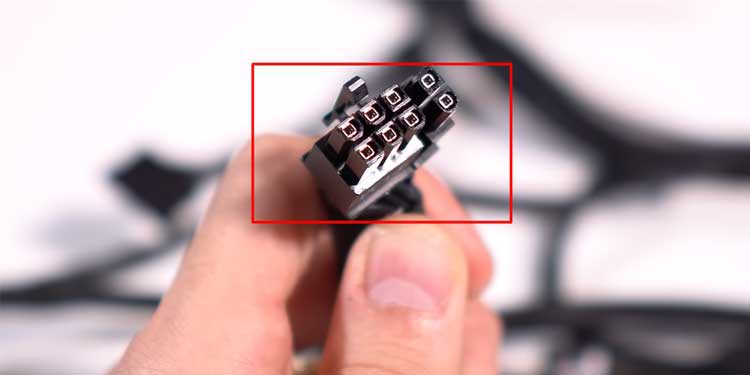
Earlier, we did not have heavier programs and we worked out with no or lower capacity video cards. These graphics cards could power themselves up by taking the elixir directly from the motherboard.However, as our desire increased, the capacity and hence the power required for the video card has risen. The graphics card that we use today may require power directly from the PSU. For that reason, the PSU manufacturers provide us with a cord with 6 pins and removable 2 pins to power up the video card.Similar to the processor, the power required for the graphics card also varies according to the type. Some require 6 pin while some require 8 pins to run it. Here is the way to connect either of them to the right port.Furthermore, there can be two different connectors, one for the video card and another for the CPU, having 8 pins on both. To differentiate which one belongs where you just have to look at the structure. The connector for the CPU has split in the middle and others mostly have split making 6 and 2 separate pins.Let’s see what job the remaining cables have on your computer.
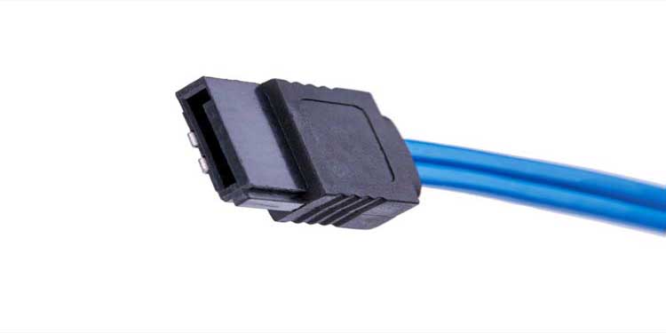
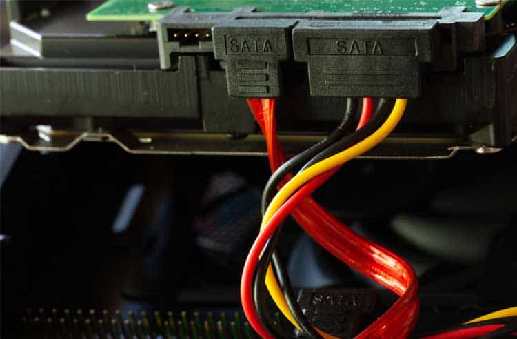
Connection of the SATA Connector
Among the Hardware in your computer that requires direct power from PSU, Hard Disk Drive, SSD, CD/DVD-Drive, etc. are some of them. These hardwares uses the mentioned SATA connector to receive the power.If you learned how to connect other connectors, then it is also equally simple. Here is the way to do it.These cables are optional to use except for the HDD or SSD. You generally get atleast 2 SATA connectors. You can leave the remaining ones untouched if you do not have additional hardware needing these.If you have become perfect at connecting the SATA cable to different hardware, let’s learn about its older brother, the Molex connector.
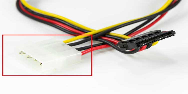
Connection of the Molex Connector
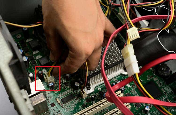
Remember the older Hard drives that had a number of pins behind it? You must also have immediately thought about the cable to power up the HDD through PSU. That cable is the Molex connector.Nowadays, the Molex connector does not have much use. However, the manufacturers of PSU like to stay on the safe side providing these cables to the unit. If some users still use the older HDD and motherboard, it is best to have at least one Molex connector in the PSU.This works similarly to the SATA cables. The SATA cables can be said as the replacement of the Molex connector.Let’s see how to recognize the Molex connector and the way to connect it.There can be an additional small 4-pin connector coming out of the PSU. This pin is similar to a Molex connector but only smaller. This pin is there to supply power to a Floppy Disk Drive.The process to connect the pin for an FDD is similar to other connectors. Most of the systems, at present, have no FDD in them and this connector is mostly rendered useless now.You have now learned the way to connect all the power cables to different parts on a motherboard with hardware. If you manage the cables cleanly with zip ties or some process, you can easily assemble all the connections in your computer.
